


Stone Look Decorative Panels with Integrated LED Channels: Electrical Safety, Heat Dissipation, and IP Rating Validation
Stone Look Decorative Panels with Integrated LED Channels: What Technical Evaluators Must Verify Before Specification
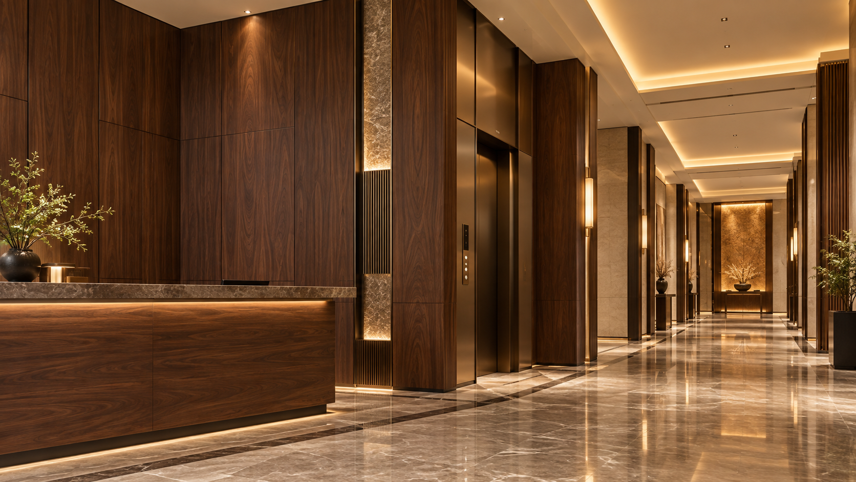
When stone-effect decorative panels arrive pre-equipped with recessed LED channels, the visual payoff is immediate—clean lines, seamless illumination, and a high-end material aesthetic. But for technical evaluators specifying these systems in commercial lobbies, hospitality interiors, or residential feature walls, the integration isn’t cosmetic. It’s an engineering interface where electrical safety, thermal behavior, and environmental resilience converge—and where assumptions can lead to non-compliance, premature failure, or field rework.
These panels aren’t just cladding with lighting bolted on. The LED channel is structurally embedded—often milled into the substrate, lined with reflective material, and sealed at junctions. That changes everything: load paths shift, heat migrates differently, and ingress protection must account for both the panel’s surface integrity and the continuity of the channel system. This article cuts past marketing claims to focus on three validation checkpoints that cannot be deferred to installation or subcontractor verification: electrical separation integrity, real-world thermal dissipation under sustained operation, and IP rating applicability beyond lab conditions.
Electrical Safety Is Not About Voltage Alone—It’s About Enclosure Integrity
Many specifiers assume that because LED strips operate at low voltage (typically 12V or 24V DC), integrated channels are inherently safe. That’s misleading. Low-voltage circuits still require proper insulation coordination, mechanical protection, and separation from other building systems—especially when routed within combustible substrates or adjacent to HVAC ducts or fire-stopping zones.
The critical question isn’t whether the LED strip meets Class II requirements—it’s whether the panel’s integrated channel design maintains required creepage and clearance distances throughout its service life. Panel flexing, thermal cycling, adhesive degradation, or even minor impact damage can compromise internal spacing. Look for evidence—not just certification marks—that the channel assembly has been tested as part of the full panel system, not as a standalone component. UL 879 or IEC 60598-1 Annex Q testing protocols matter here, but only if applied to the complete panel + channel + mounting configuration used in practice.
Also verify grounding continuity across all metal components—including aluminum extrusions, mounting rails, and any conductive backing layers. A single ungrounded section inside the channel can become a capacitive coupling path during fault conditions, elevating touch voltage beyond acceptable limits—even in low-voltage setups.
Heat Dissipation Isn’t Determined by “Ventilation Gaps”—It’s Governed by Thermal Interface Resistance
LEDs generate heat—not just at the diode junction, but along the entire current path. In integrated channels, heat transfers into the panel substrate, then outward via conduction and convection. But stone-look panels are rarely pure stone; most use composite cores (MDF, PVC, or mineral-filled polymers) with varying thermal conductivity—often below 0.3 W/m·K. That means heat doesn’t dissipate evenly. It pools locally around LED drivers, dense pixel clusters, or poorly bonded sections of the channel liner.
Thermal imaging studies of installed panels consistently show hotspots exceeding 75°C at driver locations—even when ambient temperature is 25°C and airflow is nominal. That’s well above the 60°C threshold where many standard LED drivers begin derating output or accelerating capacitor wear. Worse, sustained high temperatures degrade adhesives securing the LED strip, leading to delamination and uneven light distribution.
Effective thermal management requires more than passive air gaps. It demands verified thermal interface materials between strip and channel wall, consistent substrate density (no voids or inconsistent fill), and empirical data showing junction temperature rise under continuous 100% duty cycle—not just 30-minute lab bursts. If the manufacturer provides no thermal resistance (Rth) values for the panel-channel assembly—or offers them only for ideal lab conditions—assume worst-case derating of 25–40% in real installations.
IP Ratings Are Meaningless Unless Validated for the Full Assembly—and Its Mounting Method
An IP65 rating on a channel extrusion datasheet does not extend to the finished panel. Why? Because IP testing applies to the entire enclosure, including seams, cutouts, fastener penetrations, and transitions to adjacent materials. Stone look decorative panels are rarely installed as isolated units. They’re cut, joined, trimmed, and terminated against ceilings, soffits, or structural elements—each junction introducing potential ingress pathways.
Most failures occur not at the channel itself, but at termination points: where the panel meets a plasterboard edge, abuts a metal trim, or interfaces with a recessed ceiling grid. Dust and moisture ingress here can corrode connections, fog optics, or create tracking paths across PCB surfaces. Real-world validation requires testing the installed system—not just the panel alone—with simulated site conditions: vibration, thermal cycling, and directional water spray replicating HVAC condensation drip patterns or cleaning runoff.
Also note: IP ratings assume correct installation per manufacturer instructions. Deviations—such as using non-specified sealants, omitting gasketing at joints, or over-tightening fasteners that distort channel geometry—void protection claims. Any specification must include installation tolerances, compatible sealants, and torque limits—not just product-level IP class.
How to Validate Without Relying on Datasheets Alone
Start with test reports—not summaries, but full documents showing test setup, instrumentation calibration, pass/fail criteria, and environmental conditioning cycles. Cross-check that the tested sample matches your intended thickness, core composition, and finish type. A 12mm MDF-core panel with matte finish may behave thermally and electrically different from a 9mm PVC-core version with gloss coating—even if both carry the same model number.
Request third-party verification—not just self-declared compliance. Look for accredited labs (CNAS, UKAS, or A2LA signatories) issuing reports under ISO/IEC 17025. Pay attention to report dates: thermal aging tests older than 18 months may not reflect current production batches, especially if raw material suppliers or process parameters have changed.
Finally, inspect physical samples for consistency: uniform channel depth, absence of micro-cracks along milled edges, and precise alignment between LED strip seating and reflective liner. These aren’t cosmetic details—they directly affect thermal contact resistance and optical efficiency.
For technical evaluators, the decision isn’t whether integrated LED channels are viable—it’s whether the specific panel system has been engineered and validated as a unified electromechanical assembly. When safety, longevity, and light quality are non-negotiable, verification starts before the first cut is made.
For applications requiring comparable performance rigor but with wood-grain aesthetics and equivalent thermal and electrical integration standards, consider the High-End Wood Grain-MLMW502.
RECOMMEND

Sep 20, 2026
What Are the Risks of Standard Panels in Premium Commercial Interiors?
What are the key risks of using standard decorative panels in premium commercial interior projects? Explore fire, wear, moisture, and compliance risks.
Sep 11, 2026
How to Manage the Logistics of a Custom Decorative Panel Manufacturing Project with Multiple Suppliers?
Learn how to manage Custom Decorative Panel Manufacturing with multiple suppliers. Discover strategies for supply chain coordination, quality control, and logistics to ensure project success. Streamline your process with expert tips.
Sep 11, 2026
How to Select the Right Color Palette for Commercial Interior Panel Solutions in a Tech Startup Office?
Learn how to select the perfect Commercial Interior Panel Solutions color palette for your tech startup office. Discover the psychology of color, practical tips for durability, and how to create a productive, inspiring workspace that boosts brand identity and employee morale.
Sep 11, 2026
What Are the Most Common Mistakes When Specifying Architectural Decorative Panel Solutions for Schools?
Avoid costly mistakes when specifying Architectural Decorative Panel Solutions for schools. Learn how to ensure fire safety, acoustic performance, and durability. Our guide helps you choose panels that meet all functional requirements for safer, smarter learning environments. Click to master your specification process.